FieldVolt Instrument Power Standard
Purpose
The FieldVolt instrument power standard was established in 2024 by Leeman Geophysical LLC in collaboration with field practitioners in an effort to create a standardized power interface for geophysical field equipment. Interoperability in the field means reduced time building cables, looking up pinouts, improvising solutions, and often damaging instruments. Anything with the FieldVolt logo by the power port can be plugged into anything else with the FieldVolt logo using cables with standard pinouts and work seamlessly.
Connectors
Manufacturer
Connectors in the FieldVolt ecosystem are Amphenol Industrial connectors. The sealing method (potted, grommets, etc) is not determined by the standard as all comply with the weatherproofing requirements of field equipment.
Nomenclature
Connectors are simply named and should be referred to/labeled as described below.
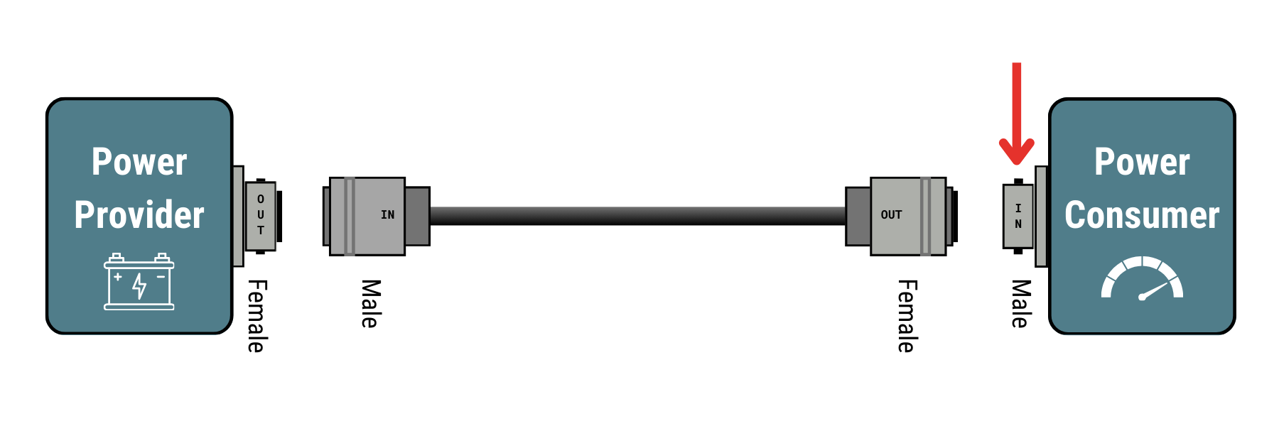
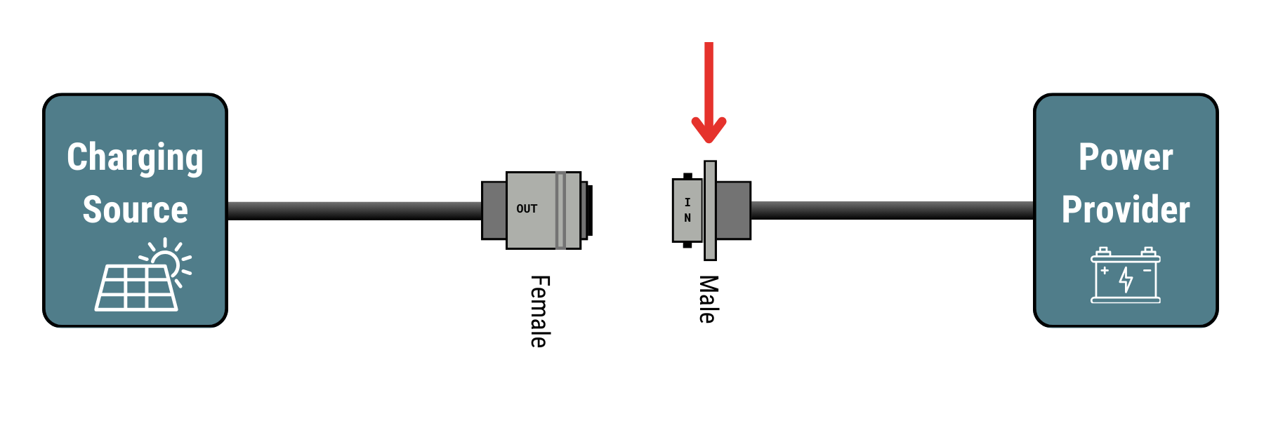
IN refers to connectors that are bringing power into a piece of equipment from an external power source. For example, the power port on a datalogger is labeled “IN”. The charging port on a portable battery box is labeled “IN”.
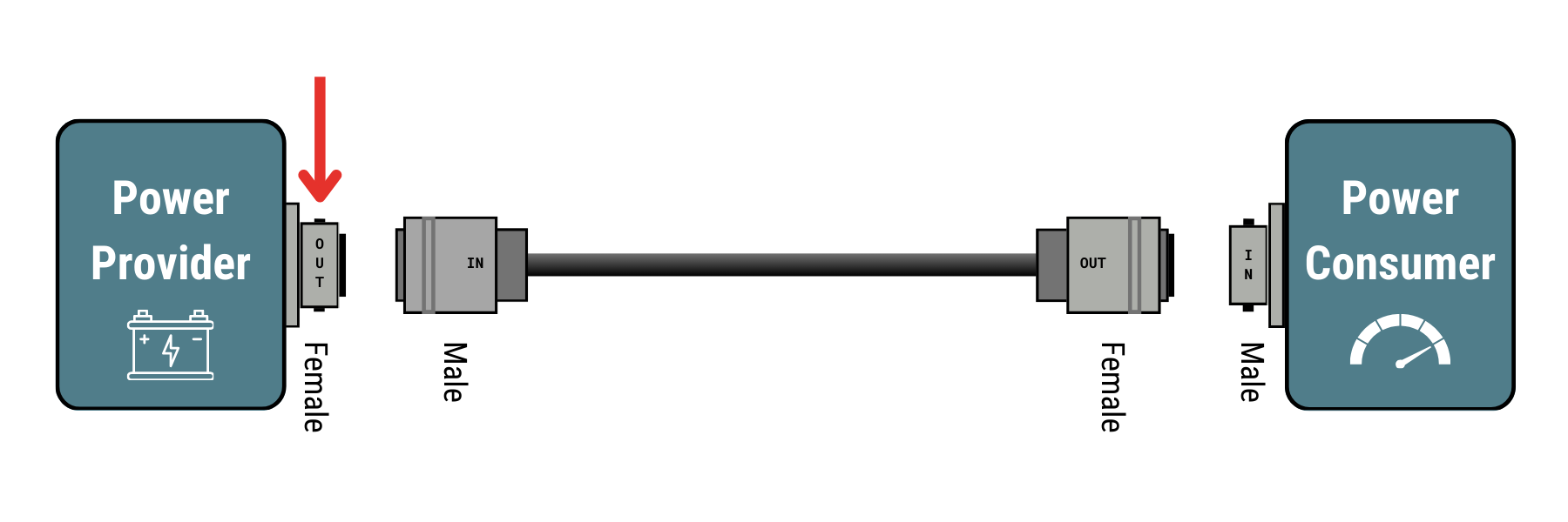
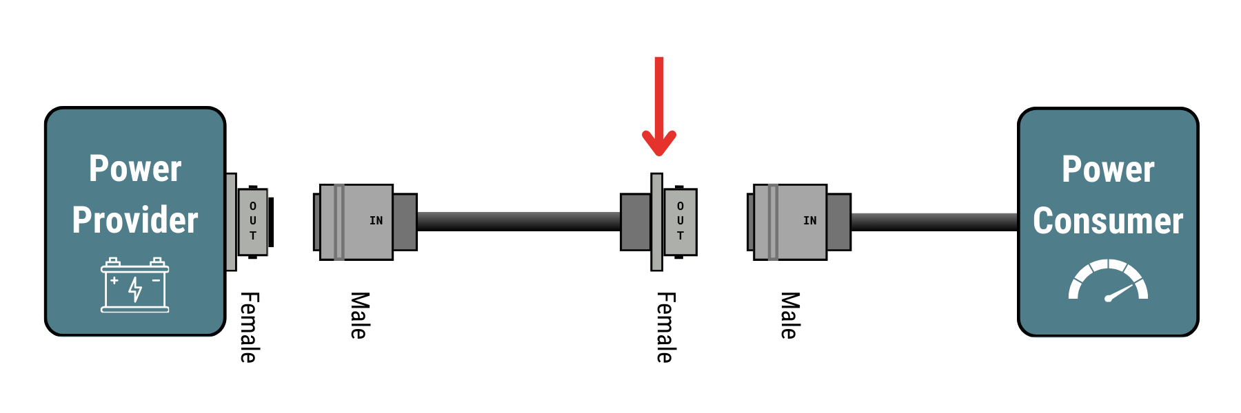
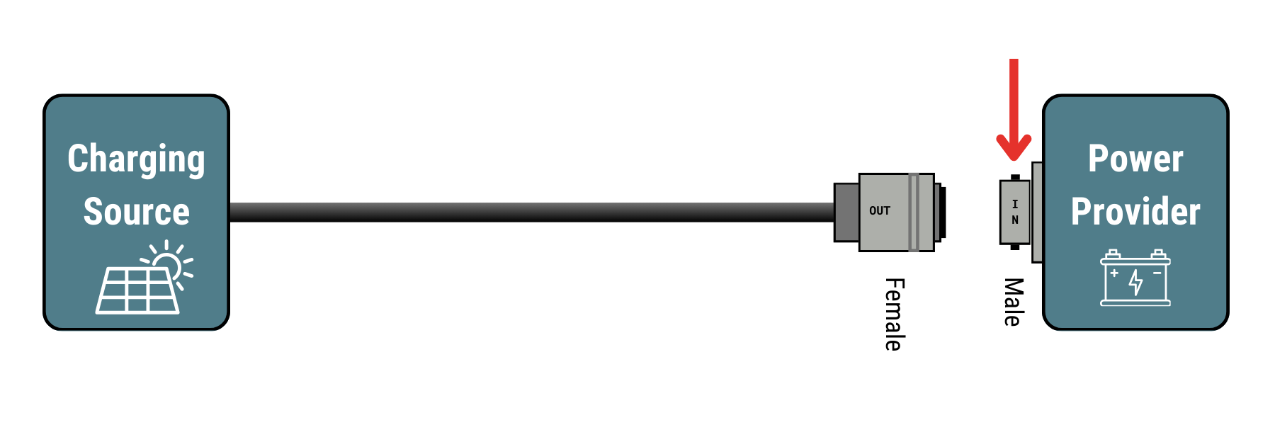
OUT refers to connectors that provide power to attached equipment. For example, the output of a battery box is labeled “OUT”, as is the output of a wall power supply or charger.
Power Consumer refers to the device (load) needing to be powered. This is the attached instrument, actuator, etc.
Power Provider refers to the current source providing power to the power consumer. This is a battery pack, wall plug, or other power source.
Charging Source refers to the device renewing the energy of the power provider. This can be a device like a solar panel or wall powered charger. Charging sources do not directly power the power consumer, but instead ensure the continued maintenance of the power provider.
Pin/Socket
Connectors with power output on them (i.e. connected to batteries, solar panels, etc) are socket connections (female connectors) to help prevent accidental shorting of connections. Connectors for power input have corresponding pins (male) connectors.
FieldVolt Logo and Name
The FieldVolt name shall be reproduced as shown in this document, as one word with a capital F and V character. The Univers font shall be used for the name or Roboto Condensed where Univers is not available. The logo for FieldVolt is available for public download below. Versions of the logo including filled, circled, and plain are provided and the one providing the most contrast on the surface it is applied to should be used.
12 VDC Field Power
12 volts DC (nominal) field power is the most common power source for geophysical field equipment. Much of this equipment has low current requirements as it is meant to be battery/solar operated for long periods of time and this standard was designed with this in mind.
The 12 VDC standard provides the following assurances:
- Be capable of providing 5A (peak) DC current at operating voltage
- Ensure 2% or less voltage drop over 5 meters of cable length at peak load
- Provide battery-safe charging (i.e. over/under voltage protection)
- Provide fused or otherwise current-protected outputs from power sources
Instruments connecting to 12 VDC field power should conform to the automotive industry operating standards at minimum:
- Operate down to 11 VDC or better
- Operate on 12 VDC nominal voltage
- Operate up to 14.3 VDC or better
- Tolerate a maximum continuous overvoltage of 16 VDC or better
- Tolerate a maximum dynamic overvoltage of 20 VDC or better
Power Connectors
Instrument power connections use a 4-pin PT series Amphenol Industrial connector of shell size 12. Common connectors and the pinout are listed below.
| Pin | Description |
| A | Positive |
| B | Not Connected |
| C | Negative |
| D | Not Connected |
Leeman Geo P/N: 1-0001497
Amphenol P/N: PT06E-12-4S(SR)
Description: Wire connector that connects to a FieldVolt ready instrument power input.
.png)
Leeman Geo P/N: 1-0001496
Amphenol P/N: PT06E-12-4P(SR)
Description: Wire connector that connects to a FieldVolt power source power output.
.png)
Leeman Geo P/N: 1-0001495
Amphenol P/N: PT02A-12-4S
Description: Panel mounted connector that would be used as a FieldVolt power source power output.
Leeman Geo P/N: 1-0001510
Amphenol P/N: PT02A-12-4P
Description: Panel mounted connector that would be used as a FieldVolt ready instrument power input.
Leeman Geo P/N: 1-0001504
Amphenol P/N: PT01E12-4S(SR)
Description: Panel mounted connector that would be used as a FieldVolt ready instrument power input.
Charging Connectors
Charging connections use a 3-pin PT series Amphenol Industrial connector of shell size 12. Common connectors and the pinout are listed below. This connector is designed to power a charge controller inside the device to be charged. There should also be a fuse or current limiting device immediately before the battery to protect both systems.
| Pin | Description |
| A | Charge Controller Positive |
| B | Negative |
| C | Not Connected |
Leeman Geo P/N: 1-0000963
Amphenol P/N: PT06E-12-3S(SR)
Description: Wire connector for charging source such as a solar panel, AC adapter, etc.
.png)
Leeman Geo P/N: 1-0001592
Amphenol P/N: PT01E12-3P-SR
Description: Wire connector for charging receiver such as solar charge controller.
Leeman Geo P/N: 1-0001494
Amphenol P/N: PT02A-12-3P
Description: Panel mounted connector to receive charging source.
Future
As the need for alternative voltage systems arises (high voltage DC downhole systems for example), more connectors will be added to the standard. These connectors shall not allow instruments which may be damaged by the different voltages to be connected. Size, shell orientation, or other manufacturer supported variations may be used to assure this. The connectors and standards will not be established until deemed necessary in an effort to keep the standard compact, easy to understand, and only containing necessary information.
Revision History
| Date | Revision |
| October 21 2024 | Add graphics and nomenclature clarifications |
| September 2024 | Added Video Overview |
| March 2024 | Initial Release |