PTM102 Precision Tilt Meter

This documentation covers part number 10-0000038
Overview
The PTM102 is the easiest to use and most versatile electrolytic geotechnical tilt meter on the market. This instrument uses two electrolytic sensor elements to determine tilts as small as sub-microradian (depending upon the range selected) on a very small power budget, making it ideally suited for remote installations with solar power or in polar environments where even solar power is limited. The instrument consists of a main circuit board and a surge suppression circuit board that can be easily changed with no soldering as a field-repair for damaged instruments. Data are output as RS-232 serial data at a user selected baud rate in a plain text format. Custom output formats can be created to integrate with other systems by request at the time of order. Data are output in raw, uncalibrated, and uncorrected form to allow the maximum versatility in post-processing. Each unit is factory tested and calibration is available from -40◦C to 60◦C.
What’s in the Box
Upon receipt of your unit, unpack the contents of the box and inspect all parts for any damage incurred during shipping. Immediately report any missing parts or damage to Leeman Geophysical for replacement. Note that there are many optional accessories available, see the accessories section of the manual for details and usage notes.
Specifications
| Parameter | Min | Typ | Max | Unit |
| DC Input | ||||
| Voltage | 6 | 12 | 28 | VDC |
| Current | - | - | - | mA |
| Environmental | ||||
| Operating Temperature | -40 | - | 80 | ℃ |
| Physcial | ||||
| Weight | - | 1.7 | - | kg |
| Width | - | 150 | - | mm |
| Length | - | 155 | - | mm |
| Height | - | 85 | - | mm |
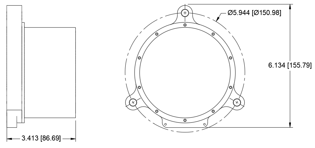
Physical Setup
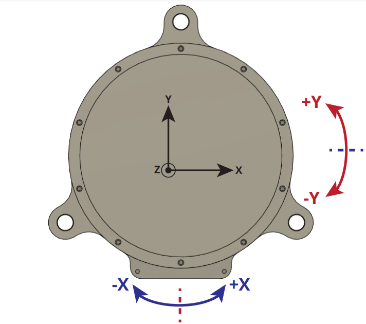
Coordinate System Convention
Coordinates of data are a right handed system with positive X indicating rotation to the ‘right’ of the instrument and positive Y indicating tilt ‘forward’ of the instrument. See the diagram below.
Mounting
Rigid Mounting
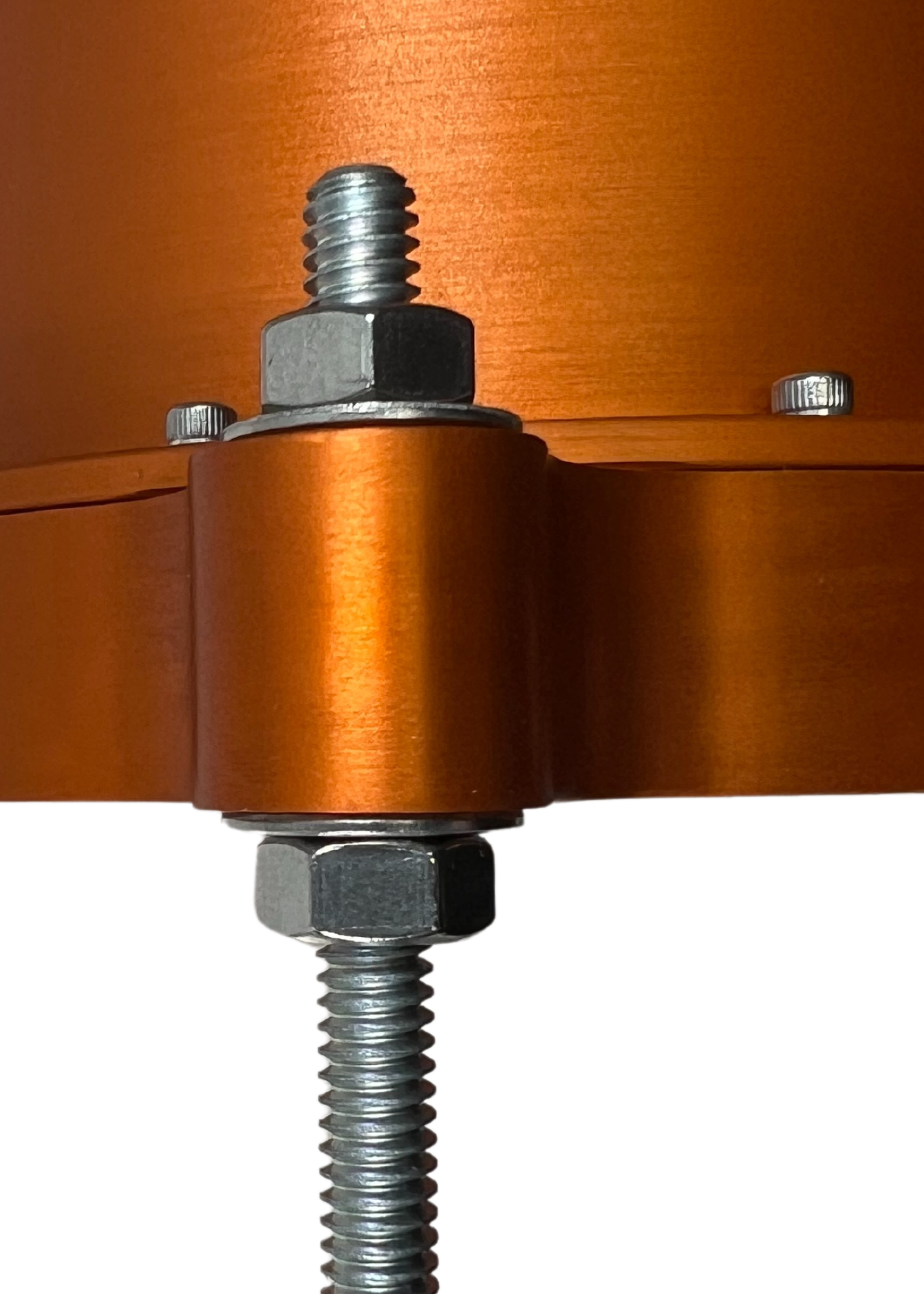
Rigid mounting of the instrument may be desired in permanent installations or in engineered structures. The tilt meter may be mounted with 1/4” hardware mounted through holes in plates/beams, on studs in a surface, or on studs epoxied into holes in a surface. If your installation environment requires custom mounting brackets or solutions please contact us before ordering to include these in your quotation.
For the most stable installation we recommend:
- Keep mounting studs short to reduce the tilt from thermal expansion/contraction.
- Use all three mounting points.
- Consider Invar studs for ultra-precision installations as they are the most thermally stable mounting available.
- If installing studs into blind holes in non-metals (concrete, rock, masonry, etc.) ensure the studs are adequately deep to be well bonded. Generally 2-4 inches (50-100 mm) is best.
Free Mounting
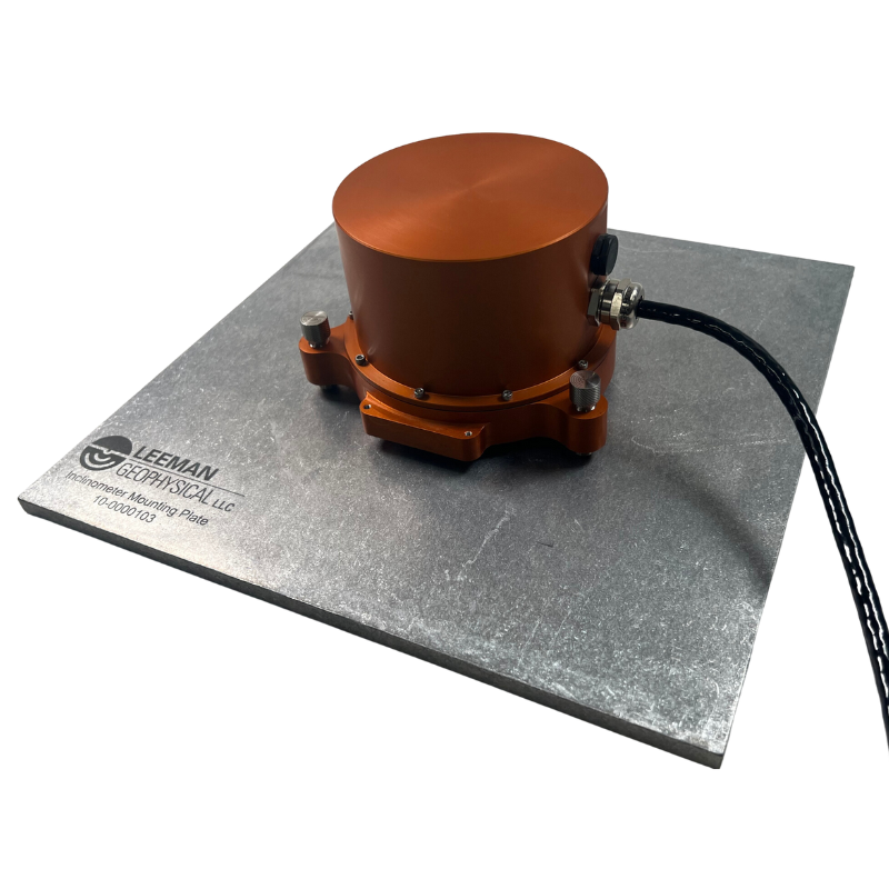
Free mounting is less permanent and may be more prone to disturbance and drift, but is often preferred for geophysical deployments. When free-mounting the instrument is sat on leveling feet on the surface to be measured. For very compliant surfaces such as snow, sand, or soil we recommend setting a plate on which to place the instrument. We offer a plate with dimples in the pattern of the leveling feet for such installations. This setup is more easily adapted in the field with fewer tools, but may be disturbed by animals and may settle under the weight of the instrument more than a rigid mounted tilt meter.
Tips for successful free mounting:
- Start with all leveling feet nearly completely retracted to minimize the stick out and reduce thermal drift.
- Use a mounting plate on loose or compliant materials.
Leveling
Leveling is the most crucial part of any deployment, especially with the ultra-precision tilt meters which have a very small linear range. All tilt meters perform best nearest zero tilt and have a linear range surrounding zero after which the response becomes non-linear and more difficult to interpret. Leveling should be done after the tilt meter is physically installed in its final location and all cables routed.
- After mounting is complete, use a level (our precision bubble level is recommended) to get the unit close to level.
- Using the optional test/setup cable, connect the tilt meter to power and to a computer.
- Using a serial terminal program, connect to the instrument. We recommend setting the instrument to TIME mode and a rate of 1Hz. (See the serial command interface section for command details.)
- Watching the values in the terminal adjust the rear two feet to get the unit as close to level as possible in the X direction.
- Using the front foot adjust Y and repeat adjustments until the unit is satisfactorily level. In many cases having both axes below 100,000 counts is satisfactory, but under 50,000 is ideal.
Orienting
After mounting the PTM102 it is important to know the orientation of each axis with respect to the Earth or other feature of interest. The back of the PTM102 enclosure has a flat that is machined to be parallel to the X-axis of the instrument. This flat was designed to allow a orienting compass, gyrocompass, or other measurement/alignment aid to be pressed against it (gently) for orientation determination.
Grounding and Transient Protection
The PTM102 contains a surge protection circuit board that is field serviceable, which often allows damaged units to be returned to service without an expensive and time consuming return to the factory. Risk of surge damage from power supply surges, nearby lightning, or other transients can be further reduced by following a few simple steps outlined below:
- Ground the instrument with a grounding rod driven within a meter of the installation. Connect the instrument using one of the #4-40 tapped holes on the orienting surface at the rear of the case. These holes may need to be cleaned with a tap to remove any corrosion or thick anodizing to ensure a solid ground connection.
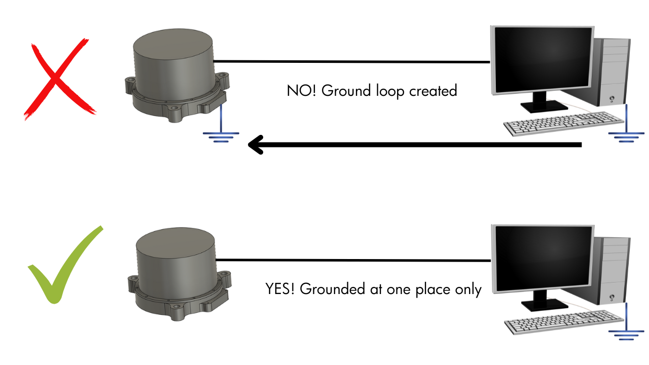
- The case on the instrument and the shield of the cable/connector are connected. Do NOT ground both ends of the cable by earth grounding connected equipment such as a computer or logger and grounding the instrument. Just ground one or the other. The resulting ground loop from grounding both ends can introduce noise and increase the risk of transient damage. This is especially important when installing with AC power as many power adapters and PCs may ground the instrument.
- Use the shortest connecting cables possible.
- Ensure the power supply is stable and well regulated.
Serial Command Interface
Settings of the tilt meter are modified via a simple serial command interface.
For more information on using a serial terminal to communicate with instruments,
be sure to read our how-to posts on the company blog (lee-
mangeophysical.com/blog). The instrument is set from the factory to 9600 baud
and to output 1 data point per second in timed output mode. Settings are stored
in non-volatile memory and kept through power cycles of the instrument. Some
settings may be over-ruled by the state of control pins on the instrument.
Commands are all followed by a newline character.
| Command | Description |
| SETBAUD X | Set the baud rate to X. |
| SETRATE X | Set the timed mode sampling rate to X samples per minute. |
| SETMODE X | Set the sampling mode to X where X is TIME or TRIG. |
| SETNAVG X | Set the numbers of samples to be averaged for each reading to X. |
| READ | Force a reading regardless of mode or time settings. |
| RESET | Restart the instrument. |
| SHOW | Show the current configuration. |
| HELP | Displays a help menu with a list of available commands. |
| DEFAULTS | Resets all stored values to the factory default values. |
SETBAUD sets the baud rate of the device to a new rate. This change takes effect immediately and the serial terminal utility will need to be disconnected and reconnected at the new baud rate. Valid rates are 1200, 2400, 4800, 9600, 19200, 38400, 57600, 74880, and 115200 baud.
SETRATE sets the output rate of data when the device is in the timed output mode. Valid values are 1, 6, 12, and 60 samples per minute. For slower sampling we recommend using triggered mode. Sampling faster than 1Hz is not allowed as the mechanical response of the electrolytic tilt sensors is on the order of several seconds.
SETMODE changes the mode of the instrument to either TIME or TRIG mode. In TIME mode the instrument will output data at the rate set by SETRATE and controlled by the internal oscillator. In TRIG mode the instrument will only output a data point when the TRIG pin is brought low. This is especially useful in very low data rate applications and compatible with our Tilt Meter Logger product.
SETNAVG determines the number of data points that will be averaged to provide a single reading. With high NAVG settings the instrument may not be able to satisfy both NAVG and the set data rate. In this case the instrument will output data as fast as is allowed by the averaging setting. The number of points to average is constrained to be in the range 1-255.
READ forces a reading to be issued from the instrument regardless of the mode, time to next data point, etc. This is useful in computer controlled acquisitions, testing, or very low rate sampling.
RESET restarts the processor of the instrument. This resets the internal time counter, but all settings are unaffected.
SHOW Display the current instrument configuration in a table suitable for saving for records or a quick visual scan.
HELP displays a condensed version of the command help menu. This is very helpful in the field as a quick reference without the instrument’s manual.
DEFAULTS resets all user select-able settings to their factory defaults. The instrument will be set at 9600 baud in timed mode with a 1Hz data output rate.
Wiring
Power Requitements
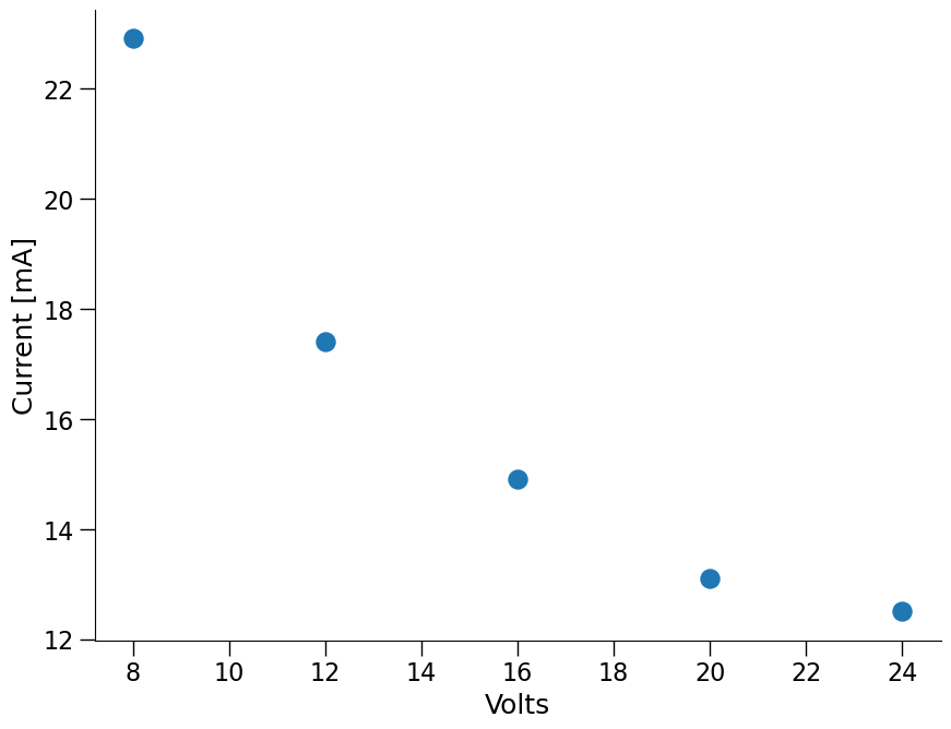
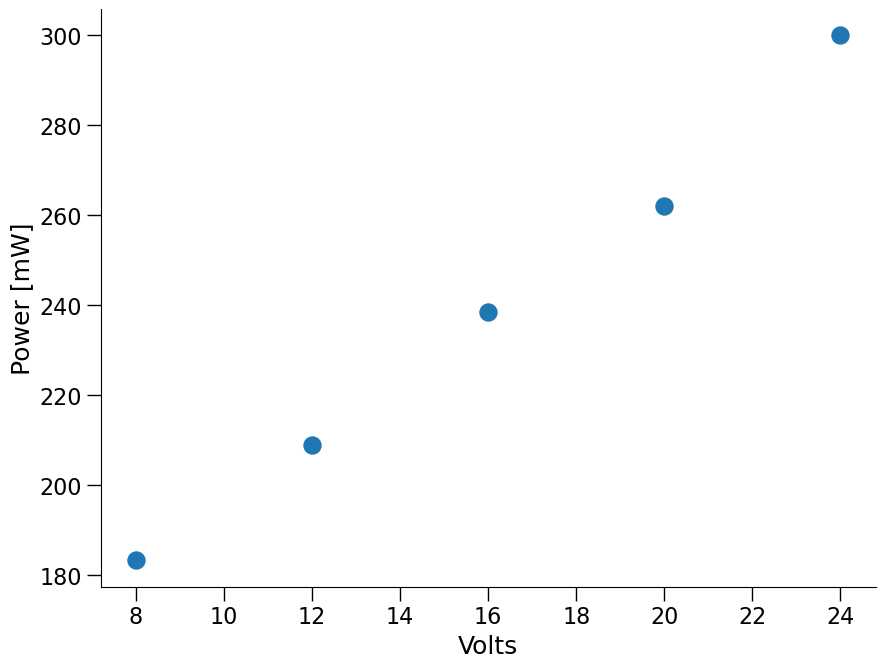
The PTM102 is a low power instrument, only drawing about 1/4W at 1Hz data rate. DC voltage from 6-28V is accepted, but ideal operation is in the 12-24 VDC range. The tilt meter is internally protected from reverse polarity connections and has a 200mA self-resetting fuse built in to the power and surge circuit board.
Connector Pin Out
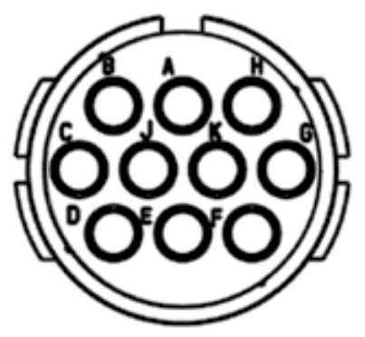
Tilt meters are equipped with a circular Amphenol style 10-pin connector. The shell is a 12 and the insert is the N (normal) orientation. Instruments have pins in a plug and connected devices have sockets in a receptacle. A mating connector such as a Souriau UTS012E10S is suitable for custom integration of the PTM102.
| Connector Pin | Function |
| A | Control 2 |
| B | Control 1 |
| C | RS232 TX from Instrument |
| D | RS232 RX to Instrument |
| E | Power Down |
| F | Unused |
| G | Ground |
| H | Instrument Power |
| J | Trigger |
| K | Unused |
Data Lines
- RS232 TX from Instrument has RS232 serial data at the user specified baud rate (default 9600) coming from the instrument to the receiving device (computer, logger, etc.)
- RS232 RX to Instrument has RS232 serial data at the user specified baud rate (default 9600) coming to the instrument from the controlling device (computer, logger, etc.)
Power Lines
- Ground is instrument and power ground.
- Instrument Power accepts 6-28 VDC (12-24 recommended) to power the instrument.
Control Lines
Control lines are all internally pulled to logic 3.3 VDC high and should be brought low to activate their associated function.
- Control 1 activates timed output mode at the specified data rate regardless of the mode setting stored in non-volatile memory.
- Control 2 activated triggered output mode regardless of the mode setting stored in non-volatile memory.
- Power Down halts instrument output. This does not save significant power and the instrument should be turned off if readings are only to be taken at very slow rates if power savings are desired.
- Trigger triggers a reading when in triggered mode.
Operation
Warm Up
Output from your tilt meter is most stable when all operating electronics and sensing elements are at a stable operating temperature. In house testing has suggested that in most all environments a 5 minute warm up is adequate to stabilize the output of the instrument. Before leveling or taking readings we recommend the instrument be turned on and allowed to warm up for minimum drift in ultra-precision applications.
Modes
PTM102s can operate in either timed or triggered mode. This mode can be set via the serial menu or modified by use of the control pin inputs to the device. These modes let the user choose between an instrument driven system running at rates of 1-60 samples per minute in timed mode or a controller driven system running at another rate (often slower) in triggered mode.
Time Mode
In timed mode the instrument sends data at rates of 1, 6, 12, or 60 samples per minute and the rate is regulated by the internal oscillator of the instrument. This mode is most useful when working with a simple logging system, running at higher data rates, or leveling the instrument. Timed mode may be activated by setting the mode using the serial commands or by pulling the Control 1 pin to a logic low state (it is internally pulled high).
Triggered Mode
Triggered mode only takes a reading when the trigger pin is pulled to a logic low state (it is internally pulled high). Triggered mode can be activated by setting the mode with serial commands or by pulling Control 2 to a logic low state (it is internally pulled high).
Output Format

Data are output as plain text ASCII characters. The first field represents the number of microseconds since the unit was powered on and took the first reading. This field will rollover approximately every 1.2 hours. The second field is the serial number of the tilt meter. Third is the X-tilt reading in raw bits followed by the Y-tilt reading in raw bits. Fifth is the temperature of the metal enclosure measured by a sensor embedded in the enclosure metal between the X and Y sensing elements. Sixth is the temperature of the circuit board. These temperatures should track one another closely with a slight delay for the thermal mass of the case. They are used when applying temperature corrections to measurements in post-processing. Both temperatures are in degrees Celsius.
Data Interpretation
Error Sources
All tilt measurements are done with gravity as the reference for what is level. This absolute reference is very well understood and even being near large masses such as mountains can be accounted for with traditional geophyscial gravimetry. When measuring minute tilts there are three main sources of error.
Temperature Error
Temperature is the largest effect dominating many tilt measurement installations. Temperature effects can be understood and calibrated out of the readings to isolate geophysical sources of tilt. Inside each tilt element the sensor contains a conductive fluid with an air bubble. As outside temperature changes the fluid expands and contracts. This changes the size of the bubble that is in contact with the sensing elements and therefore changes the sensitivity of the tilt meter. This effect can also alter the output at null tilt. We can provide calibration of your instrument in our thermal chamber from -60°C to 40°C. These numbers provide a good starting point for calibrating temperature effects out of your raw data, but can also be convolved with thermoelastic errors (discussed later) in a field calibration.
Cross-Axis and Orientation Error
Tilt sensors are manufactured to the tightest tolerances possible, but when built to survive the most rugged field environments there are some alignment errors. The sensors may not be aligned perfectly with the X and Y axes of the instrument and may therefore not be perfectly perpendicular. Often these errors are small enough compared to the signal of interest they can be ignored, but they may be corrected for with coordinate rotations traditional to seismology.
Thermoelastic Error
All materials expand and contract with temperature - this thermoelastic effect can be quite large depending on the installation environment. The tilt meter bodies are designed to minimize thermoelastic deformation between the tilt elements and the ground, but this is one source of null offset change with temperature. Consideration must also be given to the structure or surface being monitored and the mounting configuration. Large engineered structures may tilt considerably when in sunlight for example. Thermoelastic error is minimized by keeping ther- mal differences across the measurement area and instrument as small as possible. Keeping the instrument shaded so no one portion is receiving more solar radiation than another also greatly reduces thermoelastic errors.
Example
Suppose your tiltmeter is shipped to you with the following calibration at room temperature: 13713302 bits/degree. Often we ignore the offset as it can be removed as desired. If your instrument reads out 689520 bits, then we divide that by the calibration to determine the tilt to be 0.05° or about 873 microradians.
Accessories
There are a variety of accessories available to make installing, deploying, and using your tilt meter easier! Contact us with any questions on which accessories are appropriate for your deployment or for custom integration services.
Test/Setup Cable 10-0000151
This cable allows you to power and communicate with the tilt meter in a simple way for setup, leveling, or testing. The unit accepts power from an AC wall power adapter or user supplied battery and connects to the USB port of a PC for serial communications.
Precision Bubble Level 2-0000229
The precision bubble level lets you deploy instruments very close to level initially before connecting a field com- puter to fine tune the leveling. Each graduation is degree of tilt, therefore this is a three degree range level with a sensitivity tolerance of ±10%. The tool can speed up deployments and reduce frustration and fatigue during deployment campaigns.
Tilt Meter Logger 10-0000041
For applications when unattended deployment and recording is required our tilt meter logger will record data onto an SD card. The logger will either record data at a rate set on the instrument or at lower data rates down to 1 sample/hour. At low sampling rates the logger manages power to the tilt meter to reduce overall power consumption compared to non-OEM logging equipment.
Deployment Plate 10-0000103
When deploying in compliant materials the deployment plates spreads out the footprint of the instrument to reduce instrument settling. This plate has dimples for the leveling feet of the PTM102 to rest in as well as a mounting hole pattern for our MEMS inclinometer.
Invar Leveling Feet 2-0000447
For applications where thermal drift is a large factor, we offer leveling feet made from Invar, a very thermally stable nickel alloy. These feet replace the stainless steel feet that are shipped with each PTM102 and are a quick way to reduce variability in your data.
Revision History
| Date | Changes |
| April 2024 | Reformat for web and add dimensions. Minor typo correction. |
| Febuary 2023 | Hyperlink table of contents |
| January 2023 | Initial Release |