SMPL Bridge Completion
This documentation covers the following part numbers:
- 7-0000232: 120 Ω version
- 7-0000233: 350 Ω version
Overview
Introduction
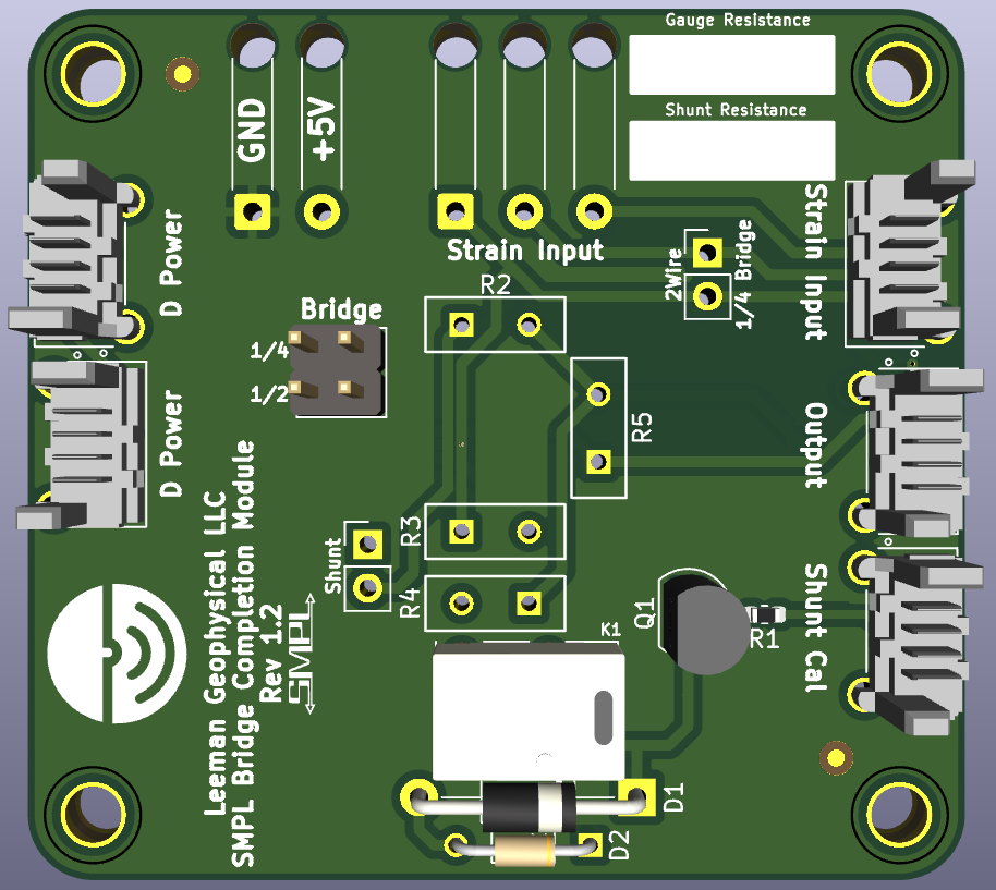
The SMPL Bridge Completion Module is a compact, configurable breakout board for interfacing strain gauges and other bridge sensors with signal conditioning equipment. It’s designed to be used in conjunction with the SMPL Load Cell Signal Conditioner or other compatible amplifiers.
The module allows users to build a full bridge from half- or quarter-bridge strain gauges using precision onboard completion resistors. It supports:
- Quarter-bridge and half-bridge configurations via jumpers
- 2-wire or 3-wire measurement modes
- Shunt calibration for system verification and gain calibration (manual or logic-triggered)
Excitation power (typically 5 VDC) is passed through the board from the SMPL Load Cell Signal Conditioner or user provided external source to the strain gauge. The completed bridge output is then routed back out for further amplification and digitization.
Each model is available in either 120 Ω or 350 Ω versions and includes a precision shunt resistor to simulate a known strain value for calibration. For maximum flexibility in field installations, the module is compatible with long lead lengths and includes jumper-selectable 3-wire compensation to minimize errors from voltage drop in extension cables.
What’s in the Box
- SMPL Bridge Completion Module (assembled PCBA)
Optional accessories such as SMPL cables and mounting hardware are available separately.
Specifications
| Parameter | Min | Typ | Max | Unit |
| Digital Control | ||||
| Shunt Control Voltage | 4.5 | 5.0 | 5.5 | VDC |
| Shunt Control Current | - | 36 | - | mA |
| Bridge Configuration | ||||
| Completion Resistance (120 Ω Model) | 119.988 | 120 | 120.01 | Ω |
| Completion Resistance (350 Ω Model) | 349.965 | 350 | 350.035 | Ω |
| Shunt Calibration Resistor (120 Ω Model) | 19998 | 20000 | 20002 | Ω |
| Shunt Calibration Resistor (350 Ω Model) | 57977.2 | 57983 | 57988.8 | Ω |
| Excitation | ||||
| Excitation Voltage | 0 | 5 | 30 | VDC |
| Physical | ||||
| Weight | - | 14 | - | g |
| Width | - | 50.8 | - | mm |
| Length | - | 54.61 | - | mm |
| Height | - | 12.7 | - | mm |
Connections
The SMPL Bridge Completion Module includes five SMPL 4-wire connectors, as well as optional through-hole solder pads for select connections. All connectors follow the SMPL Standard pinout and are labeled clearly on the PCB silkscreen.
SMPL Connector Overview
| Connector Label | Function | Notes |
|---|---|---|
| D Power (x2) | Digital power input/output | These two connectors are electrically identical and allow 5 V digital power to be daisy-chained to other SMPL boards. |
| Strain Input | Input from external strain gauge | Supports quarter- or half-bridge configurations. Follows the SMPL analog signal standard. |
| Output | Completed bridge output and excitation pass-through | This connector interfaces directly with the SMPL Load Cell Signal Conditioner, providing excitation to the bridge and routing the resulting signal back. |
| Shunt Cal | 5 V logic input to activate shunt calibration | Accepts a standard SMPL digital input signal. A logic HIGH inserts the shunt resistor into the bridge circuit. |
Notes on Usage
- The D Power connectors allow the board to receive or pass along digital logic power. You can connect either jack, or use both to daisy-chain power to additional modules. These do not provide power for the excitation, but only for the shunt calibration relay. If the shunt calibration will be done manually or not utilized, these connections may be ignored.
- The Strain Input connector is where your external strain gauge connects. The pinout matches the SMPL Standard and supports 2-wire or 3-wire mode depending on jumper configuration.
- The Output connector is designed to mate directly with the SMPL Load Cell Signal Conditioner, forming a complete signal conditioning path. You may also wire this connector to your own equipment, following the SMPL analog signal pinout.
- The Shunt Cal connector allows external logic to control the on-board shunt calibration relay. Apply 5 V to insert the shunt resistor and simulate a known strain value.
Refer to the silkscreen on the back of the PCB or the SMPL Standard for connector pinouts.
Hookup Guide
Before beginning setup, we recommend using our SMPL breakout modules to simplify connections between your external system and the Bridge Completion Module. These breakout boards provide screw terminals for fast, reliable wiring and easy servicing in the field or lab. For more permanent installations, consider using DB9 connectors for strain gauge inputs and BNC connectors for analog outputs. Standardized pinouts for all supported connector types are documented in the SMPL Standard, and matching breakout accessories are available as part of the SMPL product lineup.
Using the SMPL Load Cell Signal Conditioner
- Ensure all power is off. Do not apply power until all jumpers are configured and wiring is complete.
- Using a SMPL 4-wire cable, connect the Output connector of the Bridge Completion Module to the Load Cell connector of the SMPL Load Cell Signal Conditioner.
- Connect your strain gauges to the Strain Input connector on the Bridge Completion Module. Refer to the tables below for the connection of 2 and 3 wire configurations of half and quarter bridge circuits.
- Set the jumpers as needed (see below)
- Connect the output of the SMPL Load Cell Signal Conditioner to your digitization equipment or a multimeter
- If you intend to use the shunt calibration function and want to trigger the shunt remotely via the on board relay, connect a 5VDC supply to the SMPL D Power connectors. The control signal is connected to the Shunt Cal connector. The tables below show the connector pinouts. The digital signal is designed to be compatible with our LabJack Breakout PCBs allowing easy connection to the LabJack data acquisition infrastructure.
- Apply power to the SMPL Load Cell Signal Conditioner and adjust it (see its documentation)
Using Other Amplifiers
- Ensure all power is off. Do not apply power until all jumpers are configured and wiring is complete.
- Using a SMPL 4-wire cable, connect the Output connector of the Bridge Completion Module to the external excitation voltage and amplifier inputs according to the table below.
- Connect your strain gauges to the Strain Input connector on the Bridge Completion Module. Refer to the tables below for the connection of 2 and 3 wire configurations of half and quarter bridge circuits.
- Set the jumpers as needed (see below)
- Connect the external amplifier to your digitization equipment or a multimeter
- If you intend to use the shunt calibration function and want to trigger the shunt remotely via the on board relay, connect a 5VDC supply to the SMPL D Power connectors. The control signal is connected to the Shunt Cal connector. The tables below show the connector pinouts. The digital signal is designed to be compatible with our LabJack Breakout PCBs allowing easy connection to the LabJack data acquisition infrastructure.
- Apply power and adjust the external amplifier according to the manufacturer's instructions.
Jumper Configuration
Bridge Type (Quarter or Half)
- Use the labeled jumper pads to select quarter-bridge or half-bridge mode
- Default configuration is half-bridge
2-Wire vs. 3-Wire Mode
- In 3-wire mode, one leg of the bridge is sensed independently to compensate for voltage drop in long lead wires
- Use the appropriate jumper to enable 3-wire mode when using long cables. 3-wire mode is only available for the quarter-bridge configuration.
Shunt Calibration Mode
- The shunt calibration resistor can be:
- Inserted manually using a physical jumper
- Triggered electronically using a 5 V logic signal (connect to shunt control input)
Connector Pinouts
SMPL Connector Pinouts
Digital Power (D Power)
| SMPL Pin | Description |
|---|---|
| A | Digital Ground |
| B | 3.3 VDC (not used by this board; passthrough only) |
| C | 5 VDC (used to power the shunt calibration relay) |
| D | No Connection |
Strain Input – Half-Bridge Configuration
| SMPL Pin | Description |
|---|---|
| A | Terminal of first strain gauge |
| B | Junction point between two strain gauges |
| C | Terminal of second strain gauge |
| D | No Connection |
Strain Input – 2-Wire Quarter-Bridge Configuration
| SMPL Pin | Description |
|---|---|
| A | One terminal of the strain gauge |
| B | No Connection |
| C | Other terminal of the strain gauge |
| D | No Connection |
Strain Input – 3-Wire Quarter-Bridge Configuration
| SMPL Pin | Description |
|---|---|
| A | One terminal of the strain gauge |
| B | Sense wire connected to the same terminal as pin A (for 3-wire setup) |
| C | Other terminal of the strain gauge |
| D | No Connection |
Bridge Output
| SMPL Pin | Description |
|---|---|
| A | Negative excitation (typically ground) |
| B | Negative bridge signal |
| C | Positive excitation (typically +5 VDC) |
| D | Positive bridge signal |
Shunt Calibration Control
| SMPL Pin | Description |
|---|---|
| A | Digital Ground |
| B | 5 VDC Logic Control Signal |
| C | No Connection |
| D | No Connection |
Shunt Calibration
Each version of the module includes a precision shunt resistor:
- 120 Ω model: 20 kΩ shunt
- 350 Ω model: 57983 Ω shunt
Shunt calibration simulates a known change in resistance across one leg of the bridge, causing a predictable output voltage that can be used to verify gain and system response.
The expected change in output voltage (ΔV) due to the shunt can be calculated using:
This is typically performed by:
- Activating the shunt (manually by inserting the jumper across the shunt pins or via logic signal)
- Recording the output voltage shift
- Comparing this to the expected value for verification
- Don't forget to remove the shunt jumper or deactivate the relay!
Board Revisions and Compatibility
All boards are fully compliant with the SMPL standard.
Troubleshooting
This section provides guidance for resolving common setup and operational issues with the SMPL Bridge Completion Module.
No Output Signal Present
- Verify all wiring connections — Double-check strain gauge inputs, bridge output connections, and power supply.
- Check jumper configuration — Ensure jumpers match the intended bridge type (quarter vs. half) and wire mode (2-wire vs. 3-wire).
- Confirm strain gauge is connected — An open circuit will result in no valid bridge output.
- Verify the excitation voltage — Measure across the excitation pins on the output connector (typically 5 VDC). If voltage is missing, confirm the amplifier is supplying power and that the output connector is properly seated.
Output Signal Appears Inverted
- The polarity of the bridge may be reversed. Check the orientation of the strain gauge wiring and verify jumper settings for quarter/half bridge mode.
- If connected to a SMPL Load Cell Signal Conditioner, you can use that input inversion feature to change the sign of the output.
Shunt Calibration Has No Effect
- Confirm shunt jumper or logic signal is active — Manually insert the jumper or send a 5 V logic HIGH to the Shunt Cal connector.
- Check the relay click — You may hear a faint mechanical click when the relay activates. If not, confirm the digital power rail is connected and supplying 5 V.
- Measure bridge output with and without shunt — If no voltage shift occurs, the relay or shunt resistor path may be open or misconfigured.
Signal Instability or Noise
- Inspect grounding — Check you setup for ground loops or loose wires.
- Use 3-wire mode for long cable runs — This compensates for voltage drop in the excitation line.
- Minimize wire movement — Strain gauges can be sensitive to mechanical noise and cable strain.
- Check connector seating — SMPL connectors should be fully inserted and locked.
If you continue to experience issues, please contact Leeman Geophysical support for assistance. Photos of your setup and measured voltages will help us diagnose your system quickly.
Revision History
| Date | Changes |
|---|---|
| May 2025 | Initial draft documentation created |