KLINI Surface Inclinometer
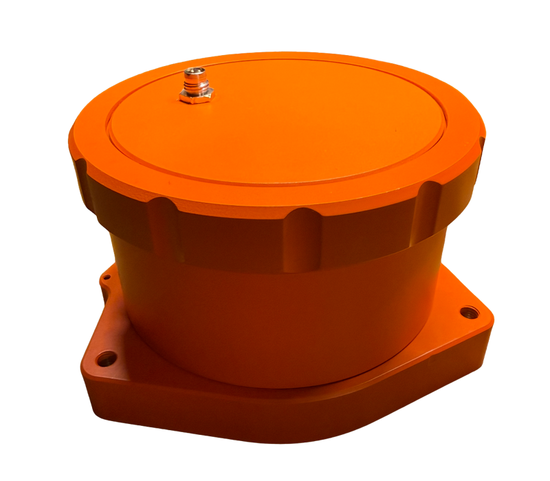
This documentation covers the KLINI 200S-M30 surface inclinometer, part number 10-0000233.
About This Manual
Firmware Versions Covered
This manual covers instrument firmware 1.1, 1.2, and 1.3. Where an instruction depends on the firmware version, a short note such as Firmware 1.2 and later follows it. A summary of changes between versions is in the Firmware Change Log.
Finding Your Firmware Version
The installed firmware version is reported in three places:
- The SHOW serial command prints a line such as
# Firmware: 1.2. - Every data file written to the microSD card starts with a header line such as
# Firmware 1.2. - The Wi-Fi settings page shows
FW 1.2next to the serial number.
Overview
The KLINI is a two-axis surface inclinometer with a built-in data logger. Each unit measures tilt on two perpendicular axes, records it to a microSD card at a configurable interval, and can stream the same readings over an RS-232 serial connection. Every reading also includes the internal board temperature and the supply voltage. A battery-backed real-time clock timestamps the data, and a temporary Wi-Fi access point provides a browser-based settings page, a live readout for leveling, and firmware updates.
Model Designations
KLINI models are named by performance class, deployment type, sensing technology, and measurement range. For example, 200S-M30 is:
| Field | Example | Meaning |
| Series | 200 | Resolution class (see below) |
| Deployment | S | Surface instrument |
| Technology | M | MEMS tilt sensors |
| Range | 30 | Specified measurement range, ±30° |
| Series | Resolution Class |
| KLINI 100 | 100 µrad and coarser |
| KLINI 200 | 10 to 100 µrad |
| KLINI 300 | 1 to 10 µrad |
| KLINI 400 | 1 µrad and finer |
The 200S-M30 uses two single-axis MEMS inclinometers, one per axis, which are most linear near level.
In firmware 1.3 and later, the SHOW command and the data file header report
the 200S-M30's sensor type as A. Firmware 1.1 and 1.2 report a component
designation instead.
Enclosure and Components
The instrument is housed in a Cerakote-coated 6061 aluminum enclosure sealed with an O-ring, and is rated IP67 when the connector is properly mated. The instrument is supplied without feet or mounting hardware. The base has three M8×1.25 threaded holes for optional leveling feet, and optional mounting plates are available; see Mounting.
The top of the enclosure (the "hat") is available in two versions: an M8 connector hat for external power and serial communication, and a power hat that holds AA batteries for self-contained operation (see Parts and Accessories and Dimensions). Battery run time depends on the logging interval and power settings.
The internal components are reached by removing the lid; see Opening and Closing the Enclosure.
The following user-serviceable components are inside the instrument:
- microSD card slot – removable storage for logged data.
- CR2032 coin cell – keeps the real-time clock running while the unit is unpowered.
- Configuration button (blue) – starts Wi-Fi configuration mode, or restores default settings if held during power-up.
- Status light – a multi-color light that reports logging and error status.
- Power switch – a slide switch on the circuit board that turns the instrument on and off.
Specifications
| Parameter | Min | Typ | Max | Unit |
| Tilt Measurement | ||||
| Axes | 2 (X and Y) | - | ||
| Specified measurement range | -30 | - | 30 | ° |
| Factory calibration range | -10 | - | 10 | ° |
| Sensitivity near level (one count) | - | 0.00179 (31) | - | ° (µrad) |
| Noise (one reading, 16-measurement average), rms | - | 0.0034 (60) | 0.005 (85) | ° (µrad) |
| Error within ±10°, rms | - | 0.007 | 0.02 | ° |
| Error within ±10°, maximum | - | 0.02 | 0.05 | ° |
| Error within ±30°, maximum | - | 0.2 | 0.45 | ° |
| Cross-axis sensitivity | - | 0.8 | 3.5 | % |
| Zero offset (not calibrated; see Factory Calibration) | - | 1.2 | 4 | ° |
| Sensitivity temperature drift, over operating range | - | ±0.9 | - | % |
| Zero temperature drift, -20 to 85 ℃ | - | ±0.85 | - | ° |
| Data Acquisition | ||||
| Logging interval | Manual, 1 s, 5 s, 10 s, 30 s, 1, 2, 5, 10, 15, 30, or 60 min | - | ||
| Tilt readings averaged per sample | 1 | 16 | 255 | - |
| Storage | microSD card up to 32 GB, one comma-delimited file per day | - | ||
| Interfaces | ||||
| Serial | RS-232, 8 data bits, no parity, 1 stop bit, 1200–115200 baud (default 9600) | - | ||
| Wi-Fi | Temporary access point for configuration only | - | ||
| DC Input | ||||
| Voltage | 5 | 12 | 24 | VDC |
| Voltage, absolute maximum | 4.5 | - | 28 | VDC |
| Power, normal operation (1 s logging) | - | 0.15 | - | W |
| Power, low-power mode | - | 20 | - | mW |
| Environmental | ||||
| Operating temperature | -40 | - | 70 | ℃ |
| Storage temperature | -40 | - | 85 | ℃ |
| Ingress protection | IP67 with connector mated | - | ||
| Physical | ||||
| Weight | - | 1.28 | - | kg |
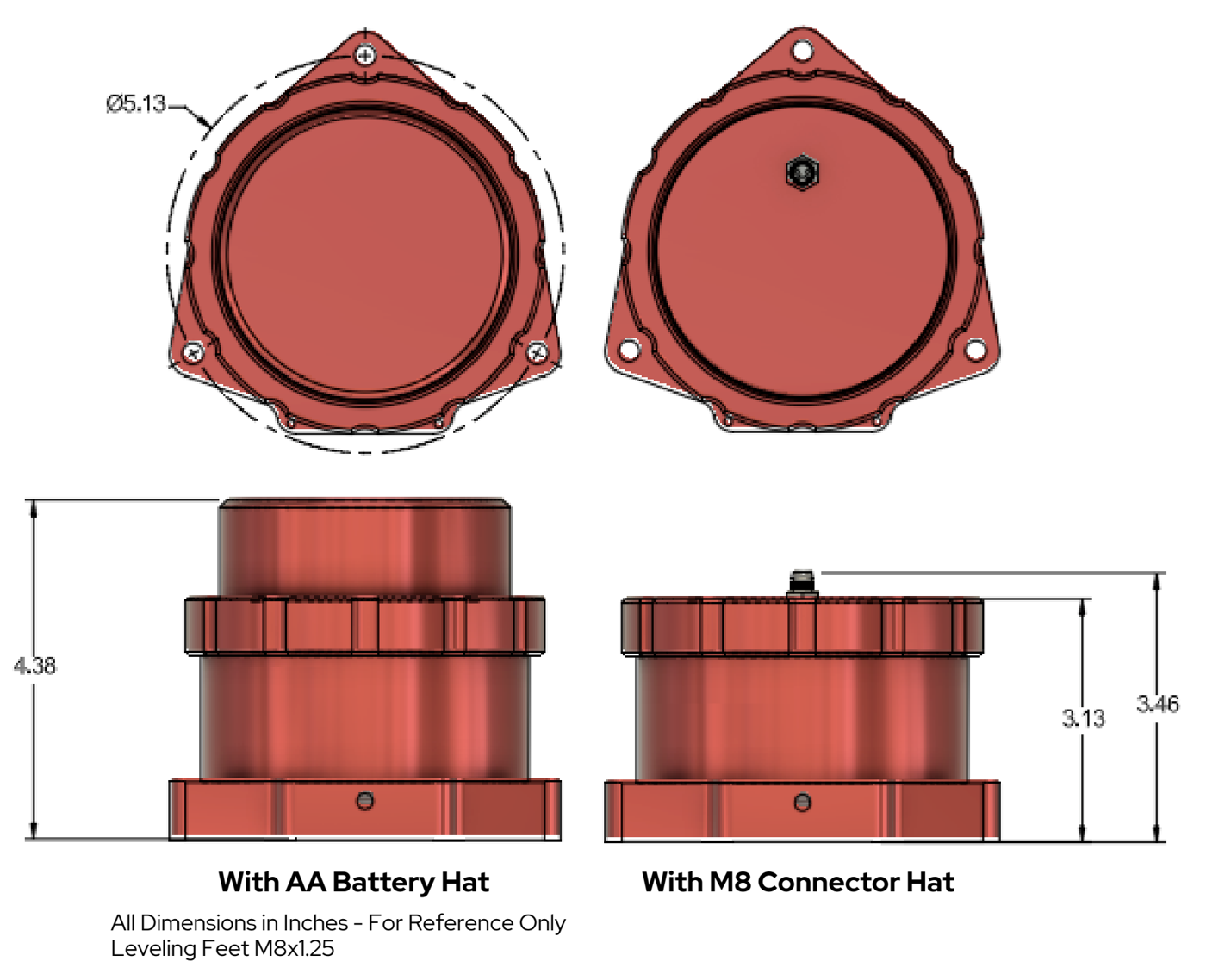
| Enclosure diameter | - | 130 (5.13) | - | mm (in) |
| Height, M8 connector hat (to connector top) | - | 88 (3.46) | - | mm (in) |
| Height, AA battery hat | - | 111 (4.38) | - | mm (in) |
| Leveling foot thread (feet optional) | M8×1.25 | - | ||
The specified measurement range is the range over which the instrument is intended to be used. The factory calibration is fitted and certified over ±10°, where the sensors are most linear; see Calibration. Error figures are relative to the factory calibration reference, at room temperature, after calibration. Noise is measured at a 1 s logging interval.
Parts and Accessories
| Part Number | Description |
| 10-0000233 | KLINI 200S-M30 surface inclinometer |
| 10-0000235 | RS232 M8 Kit (interface cable) – M8 cable and RS-232 adapter with wall-power and battery-clip power connections, for setting up, operating, and communicating with the instrument in the lab or field |
| 10-0000236 | Power hat – AA battery top for self-contained operation |
| 10-0000244 | KLINI Mounting Plate Kit – flat plate for bolting the instrument to a horizontal surface such as a floor, pad, or the top of an instrument enclosure |
| 10-0000241 | KLINI Right Angle Mounting Plate Kit – 90° plate for mounting the instrument to a vertical surface such as a post or wall |
Accessories and replacement O-rings are available from Leeman Geophysical LLC; contact us for ordering.
Installation
Always consult local codes, guidelines, and professional guidance for installation.
Connector Wiring
The 4-pin M8 connector on the connector hat provides power, ground, and RS-232 communication. The RS232 M8 Kit (10-0000235) provides a ready-made interface cable.
| Wire Color | M8 Pin | Description |
| Brown | 1 | Power |
| White | 2 | RS-232 RX to instrument from device |
| Blue | 3 | Ground |
| Black | 4 | RS-232 TX from instrument to device |
Opening and Closing the Enclosure
The lid is held by a threaded retaining ring and sealed with an O-ring.
To open the enclosure:
- Remove power from the unit, or turn off the power switch once the lid is off.
- Loosen the top retaining ring and lift the lid off.
- If the lid has pressure-sealed shut, gently pry it up using the slot provided, with a knife edge or flat-blade screwdriver. Take care not to mar the finish.
To close the enclosure:
- Check the O-ring for nicks, cracks, flattening, or debris, and replace it if necessary. A small dab of vacuum grease helps hold the O-ring in place and improves the seal.
- Set the lid on top of the enclosure and rotate it until the flat on the lid lines up with the flat on the case and the lid drops into its seat.
- Tighten the retaining ring until snug. Do not overtighten the ring; little pressure is needed to seal the O-ring.
Replacement O-rings are available from Leeman Geophysical LLC. The O-ring is an oil-resistant Buna-N O-ring, 1/16" fractional width, dash number 044.
Clock Backup Battery
The CR2032 coin cell keeps the clock running while the instrument is unpowered. If the cell is missing or exhausted and power is removed, the clock loses its time; see Troubleshooting. We recommend replacing the cell yearly for units in storage.
To replace the cell, remove power and open the enclosure. Then remove the old cell and fit the new CR2032 with the positive (+) side up, taking care not to bend its holder. Close the enclosure, apply power, and set the clock.
microSD Card
Data are logged only when a microSD card is installed. Without a card the instrument still measures and can stream readings over the serial port.
Use a microSD card of up to 32 GB, formatted FAT32 (the standard format for cards of this size). To install or remove the card:
- Remove power and open the enclosure.
- If desired, disconnect the internal cable from the M8 connector to set the lid aside: press in on the plug's tab and unplug it. The plug is keyed, so it can only be reconnected the correct way.
- Slide the metal card holder shield toward the center of the instrument, then hinge it up.
- Remove or insert the card.
- Hinge the shield down and slide it toward the outside of the instrument until it clicks.
- Reconnect the M8 connector cable if you disconnected it, and close the enclosure.
Remove power before removing the card. Readings are held in memory and written to the card in groups (see Data Files), so removing power or the card can discard up to the last 10 readings or 5 minutes of data, whichever is less.
Mounting
The instrument can be installed in several ways:
- Leveling feet (optional) – fit three M8×1.25 leveling feet into the base and set the instrument on an existing firm, flat surface such as a concrete pad, adjusting the feet to level it.
- Mounting Plate Kit – bolt the instrument flat to a horizontal surface such as a floor or the top of an instrument enclosure.
- Right Angle Mounting Plate Kit – mount the instrument at 90° to a vertical surface such as a post or wall.
- Direct burial – bury the instrument without a plate.
The leveling feet need a suitable surface to rest on. Unless you are already installing on a pad or similar surface, use one of the mounting plates or direct burial. See Parts and Accessories.
Deployment
Every deployment is different; this procedure is a guideline. Contact us for guidance on your application.
- Before going to the field, connect the unit to a computer (see Serial Interface) and configure the logging interval and other settings.
- Set the clock (we recommend UTC) and confirm the backup battery is installed.
- If data are to be logged internally, install a microSD card with adequate free space.
- Choose a stable site away from large tilt sources such as trees, and out of low areas that may flood. Install the unit using one of the mounting methods.
- Level the unit as closely as practical; the instrument is most accurate within ±10° of level. A bubble level gets the instrument very close. For finer leveling, use the live view in Wi-Fi configuration mode or streamed serial data. See AN0001: Using a Tiltmeter as a Precision Level.
- If georeferenced tilt is needed, measure and record the instrument's orientation with a compass against the flat on the back of the case (see Coordinate System).
- Connect the power and data cable, apply power, and make sure the power switch is on. The status light shows red, green, then blue during startup. Within about 15 seconds the light should begin its regular status blink (see Status Light).
- Confirm logging, then close and seal the enclosure.
Operation
Coordinate System
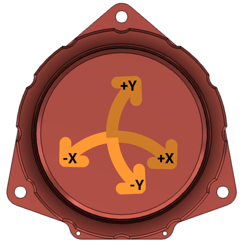
The diagram shows the instrument from above. The Y axis runs through the single mounting tab: +Y points toward that tab and -Y away from it. The X axis is perpendicular to it, with +X to the right when the tab is at the top. Tilting the instrument in the direction of an arrow gives a positive or negative reading on that axis, as labeled: lowering the +X side gives a positive X reading, and lowering the +Y side (the mounting tab) gives a positive Y reading.
The flat on the back of the case is a convenient reference for measuring the instrument's orientation with a compass. The flat is on the -Y side, opposite the mounting tab, and runs parallel to the X axis: a bearing taken along the flat toward the +X side is the direction of +X. The direction of +Y is then 90° counterclockwise from +X when viewed from above (for example, if +X points east, +Y points north). If you want to georeference the tilt data (for example, to resolve tilt into north and east components), record the orientation at installation, noting whether the bearing is magnetic or true.
The sign convention of the degree outputs is set by the factory calibration coefficients. If the coefficients are changed, the sign may change; see Calibration.
Startup
When power is applied the instrument:
- Loads its saved settings.
- Flashes the status light red, green, then blue.
- Prints
# Startup Command Window Open, waits 5 seconds for serial commands, then prints# Startup Command Window Closed. This window guarantees a chance to send commands after power-up, which matters in low-power mode (see Low-Power Mode). Otherwise, commands are accepted at any time. - Takes its first reading immediately, then continues at the logging interval.
Caution: holding the configuration button while applying power restores default settings. See Restoring Default Settings.
Sampling and Timing
Readings are taken on even clock boundaries for the selected interval. For example, with a 5-minute interval, readings are taken at :00, :05, :10, and so on. The first reading after power-up is taken immediately, whatever the time.
Each reading averages a configurable number of tilt measurements on each axis (default 16). Larger averages reduce noise but take longer.
When the interval is set to manual (0s), readings are taken only on
request with the READ command, and each one is written to
the card immediately. Firmware 1.2 and later. In firmware 1.1, 0s samples
continuously as fast as the instrument can and is not recommended; use 1s for
the fastest regular logging.
Timestamps come from the internal clock and have no time-zone marker; the clock keeps whatever time you set. We recommend UTC. The settings page labels its time field UTC, but it sets the clock to the time you enter.
Low-Power Mode
Low-power mode (off by default) reduces power consumption by sleeping between readings. It takes effect only when the logging interval is 10 seconds or longer. The instrument wakes about 3 seconds before each reading.
While asleep, the instrument does not receive serial commands or respond to the
configuration button. It is awake only briefly around each reading. To
communicate with a unit in low-power mode, remove and reapply power, then send
your command during the 5-second
startup command window, for example LOWPOWER 0 to turn low-power
mode off, or CONFIG to start Wi-Fi configuration mode. Alternatively, hold
the configuration button until the status light turns solid blue; this can take
up to about a minute.
Serial Interface
Connect to the instrument with any terminal program; see AN0005: Establishing Serial Communication with Instruments Using a Terminal Program. Use the unit's baud rate (default 9600), 8 data bits, no parity, and 1 stop bit. Type each command and end it with Enter (a newline; a carriage return is ignored). Commands are case sensitive and must be typed in upper case.
The instrument replies OK when a command succeeds and
! when it is rejected, for example because of an invalid value.
Informational lines begin with #.
When serial streaming is on (the default), each reading is also printed as a line in the same column order as the data files:
2026-09-25T17:13:17,24.188,12.014,-1002,-760,-1.794,-1.361
Streamed lines show temperature with three decimal places; data files use two. See Data Interpretation for the columns.
Serial Commands
Settings changed by command are saved immediately and kept through power cycles.
| Command | Description | Valid Values | Default |
| SHOW | Show status, settings, calibration, SD card state, and errors | - | - |
| HELP | List commands | - | - |
| READ | Take a reading now. Firmware 1.2 and later. | - | - |
| SETRATE interval | Set the logging interval | 0s, 1s, 5s, 10s, 30s, 1m, 2m, 5m, 10m, 15m, 30m, 60m | 1s |
| TILTNAVG n | Set the number of tilt measurements averaged per reading | 1–255 | 16 |
| SETTIME YYYY MM DD hh mm ss | Set the clock (24-hour time) | Years 2000–2099 | - |
| SETBAUD rate | Set the serial baud rate | 1200, 1800, 2400, 3600, 4800, 7200, 9600, 14400, 19200, 28800, 38400, 57600, 115200 | 9600 |
| STREAM 0|1 | Turn serial output of readings off (0) or on (1) | 0, 1 | 1 |
| LOWPOWER 0|1 | Turn low-power mode off (0) or on (1) | 0, 1 | 0 |
| LOWVCUTOFF 0|1 | Turn the low-voltage cutoff off (0) or on (1) | 0, 1 | 0 |
| SETLOWV cutoff reconnect | Set the low-voltage cutoff and reconnect voltages in volts | Both above 0; reconnect greater than cutoff | 11.6, 12.0 |
| SETLEDBRIGHT level | Set the status light brightness | 1 or LOW, 2 or MED, 3 or HIGH | HIGH |
| CONFIG | Start Wi-Fi configuration mode. Firmware 1.2 and later. | - | - |
| RESET | Restart the instrument | - | - |
| DEFAULTS | Restore default settings, keeping serial number and calibration | - | - |
- SHOW prints the serial number, firmware version, whether the clock is set, the current time, all settings, the calibration coefficients, the status light pattern, the SD card state and free space, and any active errors.
- READ takes one reading immediately, prints it if streaming is on, and logs it. With the interval set to
0sthe reading is written to the card at once. It can also be used between scheduled readings, for example for event-triggered measurements. Firmware 1.2 and later. In firmware 1.1 this command is not available. - SETRATE sets the logging interval.
0sselects manual readings (see Sampling and Timing). - TILTNAVG sets how many tilt measurements are averaged into each reading.
- SETTIME sets the clock when the command is received. For example, to set 26 March 2026 at 13:05:30, send
SETTIME 2026 03 26 13 05 30. After setting the clock we recommend removing power briefly and checking the time with SHOW, which confirms the backup battery. - SETBAUD saves a new baud rate, which takes effect at the next power-up or RESET. Reconnect your terminal at the new rate.
- STREAM controls whether readings are printed on the serial port. Logging to the card is not affected.
- LOWPOWER controls low-power mode.
- LOWVCUTOFF and SETLOWV control the low-voltage cutoff.
- CONFIG starts Wi-Fi configuration mode. In firmware 1.1, use the configuration button instead.
- RESET replies
OK, then restarts the instrument. - DEFAULTS restores default settings; see Restoring Default Settings.
The instrument also accepts calibration commands (described under Calibration) and factory commands. SETVINCAL, SETTEMPCAL, and SETTEMPCOMP are for factory use; changing them affects the accuracy of the voltage, temperature, and tilt readings.
Setting the Clock
Set the clock with the SETTIME command, or from the settings page in
Wi-Fi configuration mode (Time (UTC), then
Set Time). SHOW reports RTC Set: YES once the clock holds a valid time.
In firmware 1.3 and later, while the clock has lost its time and has not been
set, SHOW and the live view list the error RTC Time Invalid and the status
light shows a red single blink. The settings page also rejects an invalid date
or time.
Wi-Fi Configuration Mode
Wi-Fi configuration mode provides a settings page, a live readout, and firmware updates from any phone or computer with a web browser. Logging and serial output stop while the mode is active.
To start configuration mode, either:
- press the configuration button once the startup sequence has finished, or
- send the
CONFIGcommand. Firmware 1.2 and later.
The status light turns solid blue. The instrument creates a Wi-Fi network
named CONFIG followed by the serial number (for example CONFIG538). The
network password is included in your unit's paperwork, or you can obtain it by
contacting us. You can change it on the settings page (Security, minimum 8
characters).
Connect to the network and browse to the address printed on the serial port as
# AP IP: (normally http://192.168.4.1).
Configuration mode ends when you press Save or Exit on the settings page, or 5 minutes after it started, whichever comes first. The instrument then resumes normal operation. The 5-minute limit counts from when the mode started, not from your last action, so save changes promptly.
Settings Page
The settings page provides the same settings as the serial commands:
- Logging – log interval (Disabled is the manual
0ssetting), serial streaming, baud rate, and tilt averaging. - Time (UTC) – sets the clock from the date and time you enter.
- Power – low-power mode, low-voltage cutoff, cutoff and reconnect voltages, and status light brightness.
- Calibration – the calibration coefficients. Do not edit these unless instructed; see Calibration.
- Security – the configuration network password. Leave blank to keep the current password.
Pressing Save stores all fields on the page and ends configuration mode. In firmware 1.3 and later, invalid entries (for example a zero calibration slope, or a cut-on voltage below the cutoff) are outlined in red, and the reason appears in a red bubble when you select or point at the field. Save is blocked until they are corrected. If an invalid value reaches the instrument anyway, it shows Settings Not Saved and changes nothing. Baud rate changes take effect at the next power-up.
Live View
The Live page shows the current time, X and Y tilt in degrees, supply voltage, internal temperature, and any active errors, updated once per second. Live values are single unaveraged measurements shown to two decimal places, which is convenient for leveling. Logged data are averaged and more precise.
Status Light
During normal operation the status light shows a short pattern every 10
seconds. In low-power mode the light stays off while the instrument sleeps, so
the pattern appears only when it wakes, which can be up to about a minute
apart. Brightness is set with SETLEDBRIGHT or on the settings page. SHOW
reports the current pattern by the name in the second column.
If more than one condition applies, the pattern highest in the table is shown.
| Pattern | SHOW Name | Meaning |
| Red double blink | Red Double | An error is active. SHOW lists it; see Troubleshooting. |
| Red single blink | Red Single | A warning; readings are still being logged. Either the clock has lost its time and has not been set, so timestamps are wrong (SHOW lists RTC Time Invalid; set the clock), or the card has 50 MB or less free (SHOW lists Storage Nearly Full; copy data off and clear or replace the card). Firmware 1.3 and later. |
| Yellow single blink | Yellow Single | No microSD card installed, with low-power mode on and an interval longer than 10 s. |
| Green single blink | Green Single | No microSD card installed; readings are not logged. |
| Yellow double blink | Yellow Double | Logging to the microSD card, with low-power mode on and an interval longer than 10 s. |
| Green double blink | Green Double | Logging to the microSD card. |
| Short red flash, then yellow | Red/Yellow Fast | A card is installed but has not yet been confirmed. This is normal briefly after a card is inserted while the instrument is powered: the instrument checks a new card within about a second, or when it next wakes in low-power mode. If it persists, check the card. |
Other indications:
| Pattern | Meaning |
| Red, green, then blue, half a second each | Startup (see Startup). |
| Three green blinks | Default settings restored: after DEFAULTS, or at power-up (before the startup colors) when the configuration button is held or the saved settings were found invalid. See Restoring Default Settings. |
| Solid blue | Wi-Fi configuration mode. |
| No light | The instrument is off (power switch or supply), the low-voltage cutoff is active, or it is asleep in low-power mode. |
In firmware 1.1 and 1.2, an unset clock or a nearly full card does not change
the status light, and a card that cannot be written to or is full shows the red
and yellow pattern instead of a red double blink. Those versions also update
the logging and no-card patterns only when they next write to the card, which
can be several minutes later in low-power mode. Those versions also report
the yellow double blink in SHOW as Red/Yellow Fast, and the red and yellow
pattern as Unknown Pattern.
Low-Voltage Cutoff
The low-voltage cutoff (off by default) protects batteries from deep discharge. When enabled, the supply voltage is checked every minute. If it falls to the cutoff voltage or below, the instrument writes any buffered readings to the card and shuts down. It checks again every 10 minutes and resumes operation only when the voltage has recovered to the reconnect voltage. No readings are taken while the cutoff is active. The defaults are 11.6 V cutoff and 12.0 V reconnect.
Restoring Default Settings
Send DEFAULTS, or hold the configuration button while applying power. The
status light blinks green three times to confirm. The serial number and all
calibration coefficients are kept; every other setting returns to its default.
The instrument also restores defaults by itself at power-up if its saved settings are found to be invalid, again blinking green three times before the startup colors. In firmware 1.3 and later it keeps the calibration coefficients in this case, provided they are themselves valid. In firmware 1.2, any invalid saved value caused the calibration to be lost as well.
The defaults are:
| Setting | Default |
| Logging interval | 1 s |
| Tilt averaging | 16 |
| Serial baud rate | 9600 |
| Serial streaming | On |
| Low-power mode | Off |
| Low-voltage cutoff | Off, 11.6 V cutoff, 12.0 V reconnect |
| Status light brightness | High |
| Configuration network password | Factory password |
The clock is not changed.
Firmware Updates
Leeman Geophysical provides firmware updates as a single .bin file. Settings,
the serial number, and calibration coefficients are kept through updates
between the firmware versions covered by this manual.
- Record your settings with
SHOWand keep the output. - Start Wi-Fi configuration mode and connect to the instrument's network.
- Click Firmware update at the bottom of the settings page, or browse to
http://192.168.4.1/firmware(use the address printed on the serial port if it differs). - Choose the
.binfile and upload it. Keep the instrument powered and nearby until the page reports Firmware Installed (when updating from firmware 1.3 or later) or Update successful - rebooting now. (from firmware 1.1 or 1.2). The instrument then restarts and its Wi-Fi network disappears. - After the restart, run
SHOWto confirm the new firmware version and your settings.
If an upload fails or is interrupted, the instrument keeps running its
previous firmware. When the installed firmware is 1.3 or later, the page
reports Update Failed in that case; always confirm the version with
SHOW after an update. Try again, and contact us if the problem persists.
Calibration
Each instrument is calibrated at the factory, and the calibration coefficients are stored in the instrument and applied to every reading. A calibration report is supplied with each unit.
Factory Calibration
The factory calibration determines each axis's sensitivity by tilting the instrument through known angles on a precision tilt stage. The certified coefficients are fitted over ±10°, the range the instrument is designed to operate in. The report also shows performance over the stage's full sweep as a range check.
The calibration establishes sensitivity, not absolute level. Where the instrument reads zero depends on how it sits on its mounting surface and on small offsets in the sensors. The instrument is not certified to read zero when exactly level; set or record your zero at installation. To measure the offset directly, see AN0003: Measuring Tiltmeter Bias.
How Readings Are Calculated
For each axis the instrument converts the raw sensor count to degrees with:
where \(k\) is the slope (g per count), \(b\) the offset (g), \(T\) the internal temperature in ℃, and \(a_k\), \(c_k\), \(a_b\), \(c_b\) the temperature compensation terms. The factory sets the temperature compensation terms to zero unless otherwise stated in your calibration report, so the conversion reduces to \(\theta = \arcsin(k \cdot \text{raw} + b)\). If the value inside the arcsine falls outside ±1, the reading is limited to ±90°.
Near level this is very nearly linear: one count corresponds to about 0.00179° (31 µrad).
Viewing the Calibration
SHOW lists the coefficients as X slope, X offset, Y slope, Y offset,
followed by the temperature compensation terms. Each data file header lists
the same values.
In firmware 1.1 and 1.2 these values are displayed rounded to six decimal
places, so a slope such as -0.0000311099 appears as -0.000031. The
instrument stores and uses the full value; the rounding affects the display
only. Use the values on your calibration report. Firmware 1.3 and later
display the full value.
Changing the Calibration
You may need to change the coefficients to apply a calibration from a recalibration, or to restore factory values. Use:
SETTILTCAL X slope offset
with the axis (X or Y), the slope in g per count, and the offset in g,
exactly as printed on your calibration report. For example:
SETTILTCAL Y -3.110999e-05 0
The instrument replies OK and saves the values immediately. Confirm the
change by comparing a streamed or logged reading with the formula above.
Slopes must be non-zero; offsets may be zero. Firmware 1.3 and later reject a
zero slope: the command replies !, and the settings page marks the field as
invalid and will not save.
Caution for firmware 1.1 and 1.2: never enter a slope of zero. In firmware 1.2, a zero slope makes the saved settings invalid at the next power-up, and the instrument restores all defaults without keeping its calibration. In firmware 1.1, a zero slope makes that axis read zero. In either case the factory coefficients must be re-entered.
Changing the sign of a slope reverses the direction of that axis.
Data Interpretation
Data Files
Data are stored in a LOGS folder on the microSD card, one file per day,
named by date from the instrument's clock:
LOGS/YYYYMMDD.csv
If the file for the day already exists, new data are appended. A new file begins with a header recording the serial number, firmware version, tilt sensor type, averaging, logging interval, and all calibration coefficients. The header is written only when the file is created; it is not repeated if settings change later that day.
Readings are held in memory and written to the card every 10 readings or every
5 minutes, whichever comes first, and immediately for manual (0s) readings
in firmware 1.2 and later.
An example file:
KLINI data log SN:538
Firmware 1.2
X Tilt Sensor Type: ...
Y Tilt Sensor Type: ...
Tilt Points Averaged: 16
Log Interval: 1s
X Tilt Calibration Slope: ...
...
timestamp,temperature_C,vin_V,tilt_x_raw,tilt_y_raw,tilt_x_deg,tilt_y_deg
2026-09-25T17:13:17,24.19,12.014,-1002,-760,-1.794,-1.361
The sensor type line shows a model designation such as A in firmware 1.3 and
later, and a component designation in firmware 1.1 and 1.2.
| timestamp | temperature_C | vin_V | tilt_x_raw | tilt_y_raw | tilt_x_deg | tilt_y_deg |
|---|---|---|---|---|---|---|
| 2026-09-25T17:13:17 | 24.19 | 12.014 | -1002 | -760 | -1.794 | -1.361 |
- timestamp – date and time of the reading from the instrument clock,
YYYY-MM-DDThh:mm:ss, with no time-zone marker. We recommend setting the clock to UTC. - temperature_C – internal board temperature, ℃.
- vin_V – supply voltage measured inside the instrument, volts.
- tilt_x_raw, tilt_y_raw – averaged raw sensor counts. Use these to apply a different calibration in post-processing.
- tilt_x_deg, tilt_y_deg – tilt in degrees with the stored calibration applied, three decimal places.
To convert degrees to microradians, multiply by 17,453.3. For more on working with count data, see AN0002: Understanding Tiltmeter Count Readings.
Tilt Interpretation
Tilt data include instrument effects as well as the tilt under study. The factors below should guide deployment and analysis. Our application notes cover several of them, and we are happy to help.
- Zero offset – the reading when level includes small sensor and mounting offsets. Most studies use changes in tilt, so record the initial reading or remove it in processing.
- Range – the instrument is most accurate within ±10°. Beyond this, errors increase; the report's range check shows the behavior of your unit.
- Temperature – temperature changes can alter the sensor offset and sensitivity and cause thermal expansion of the enclosure and mounting. These effects are usually corrected together by comparing tilt with the logged temperature.
- Cross-axis tilt – small misalignments between the sensing axes and the enclosure produce a small signal on one axis when the other tilts.
- Mounting – an unstable mounting surface produces tilt unrelated to the process under study.
Troubleshooting
Run SHOW for the error list and SD card status.
| Symptom | What to do |
| No response on the serial port | Check wiring, power, and the baud rate (default 9600; a changed rate applies after restart). If low-power mode is on, remove and reapply power and send the command during the 5-second startup window. If the baud rate is unknown, try each supported rate. |
Command returns ! |
The command or a value was not accepted. Commands are upper case and values must be in the valid range. READ and CONFIG are not available in firmware 1.1. |
SHOW reports RTC Set: NO or the error RTC Time Invalid (firmware 1.3 and later), or timestamps are in the year 2000 |
The clock lost its time while unpowered. Replace the backup battery and set the clock. In firmware 1.3 and later the status light shows a red single blink until the clock is set. |
| Green or yellow single blink; no data files | No microSD card detected. Install a card. |
Red double blink with SD Mount Failed or File Open Failed |
Check the card is seated and formatted FAT32. Try another card. |
Red double blink with SD Write Failed (firmware 1.3 and later) |
Readings could not be written to the card and are not being saved. Copy data off, and clear, reformat, or replace the card. |
Red double blink with Storage Full (firmware 1.3 and later), or SD status FULL / BLOCKED |
5 MB or less remains on the card. Copy data off and clear or replace the card; a full card cannot store new readings. |
Red single blink with Storage Nearly Full (firmware 1.3 and later), or SD status NEAR FULL |
50 MB or less remains; readings are still being logged. Copy data off and clear or replace the card before it fills. |
| Short red and yellow flashes that persist | A card is installed but writes are not being confirmed. In firmware 1.1 and 1.2 this is how a full or failing card appears. Check the SD status with SHOW. Copy data off, and clear, reformat, or replace the card. |
Red double blink with RTC Error, Temperature Sensor Error, Input Voltage Sensor Error, or GPIO Initialization Failed |
A hardware check failed at startup. Remove power, wait, and reapply. If the error persists, contact support. |
| Three green blinks at power-up that you did not cause | The saved settings were invalid and defaults were restored. Check your settings and calibration coefficients with SHOW against your calibration report. |
| Instrument stops logging on battery power | The low-voltage cutoff may be active. Check the battery; logging resumes when the voltage reaches the reconnect voltage. |
Cannot find the CONFIG Wi-Fi network |
Confirm the light is solid blue. Configuration mode ends after 5 minutes; start it again. |
| Tilt reads ±90° or a constant value | Check the calibration coefficients with SHOW against your calibration report. |
Firmware Change Log
Changes that affect customers. Firmware 1.1 was the first customer release.
| Version | Changes |
| 1.3 |
|
| 1.2 |
|
| 1.1 |
|
Dimensions
All dimensions in inches, for reference only. Leveling feet are M8×1.25. The drawing shows the enclosure with the power hat (left) and with the M8 connector hat (right).
Revision History
| Date | Changes |
| September 2026 | Initial release. |